Sonoluminescence
Answers and How To
History: Sonoluminescence was discovered by accident in
the early 1930's by a pair of German Physicists at the University of Cologne. It hasn't
been until the last ten years that theorists and researchers have really given
sonoluminescence an audience. The leading work has being done by Seth J. Putterman,
Robert A. Hiller and Bradley P. Barber at UCLA. While this group has published many
papers on sonoluminescence the most popular of their papers can be found in Scientific
American Feb. 1995 Vol.272.
Overview: The phenomenon of single bubble
sonoluminescence (SBSL) can be produced as a table top physics project. From 100 to 200
dollars one can make sonoluminescence. To make SBSL one has to have a bubble (of plain
air) surrounded by water in a spherical flask and then bombarded by high frequency sound
waves. This causes the bubble to contract and as this happens something very spectacular
happens! The bubble starts emitting light. Light, as in photons are being emitted from
this bubble of air (now plasma) that is under contraction.
Specifics: As if the emitting of light isn't strange
enough one also has tremendous pressures and temperatures that turn the air in the
bubble into plasma. Temperatures have been estimated to range from 10 to 100eV (1eV =
11,600K or 20,420 degrees F). O.k. the number you want is 2,042,033 degrees F @ 100eV;
that is as hot as the corona of our sun. The pressures are as high as 200Mbar (1Mbar =
10^11 Pa) in the core of the imploding bubble. This pressure is equal to 1.974*10^8 or
19,743,336 atm (atmospheres). One atmosphere is the amount of pressure that we live in
at sea level. The use of different gases has also shown a very peculiar happening. If
the surrounding water is doped with 1% Argon gas the emission of light grows by a factor
of >100. Other noble gases also have shown an effect on the amount of photons emitted.
Theories of Sonoluminescence: Into the unknown now. The
Physics community is presently working on hypotheses for the mechanisims of
Sonoluminescence.
1) One of the most dynamic of hypotheses on SL is one provided by Claudia Eberlein. She
proposes that the 12ps flashes of SL is generated by photons being emitted by Hawking
Radiation. This is the same radiation that is generated by a black hole. Comparitive to
other hypotheses the Hawking Radiation model correlates predicted and actual
temperatures quite nicely.
2) Another is the Properetti's Theory. This theory states that Sonoluminescence takes
place due to tiny jets of liquid shooting across the bubble's interior. These proposed
jets are traveling at supersonic speeds (Mach 4, Putterman) and when a jet would slam
into the side of the bubble opposite of the projection side it would fracture. When the
jet "fractures" it would release energy in the form of light. This theory could also
help with theunderstanding of why the use of noble gases in the surrounding liquid can
increase the photon output. Prosperetti believes that the addition of the innate noble
gases creates flaws or weaknesses in the water's crystal-like structure providing the
fractures a foothold in which to begin. This would increase the amount of fractures that
would take place in the Sonoluminescencing bubble. Hence the emission would be increased.
Equipment (required):
any function generator working around 25 kHz, adjustable to +/- 1 Hz
(+/- 10 Hz may work, too)
nearly any kind of audio amplifier will do. If you're not sure, measure the saturation voltage:
40 V peak-to-peak should be enough.
around d=16 mm in diameter, h=8 mm thick
around 3 mm in diameter, 1 mm thick
take a 100 ml Pyrex/Duran spherical flask, diameter 65 mm, with a small neck. An
industrial one has poor optical quality, so better take a free blown one.
or
Equipment (nice to have, but not necessary):
- second oscilloscope
- vacuum pump
- high-pass filter
- laser
Set up the assembly:
- Prepare the transducers:
They are polarized, so when connecting them in parallel watch out for the mark on the electrodes. Do not connect them antiparallel. Clean the electrodes of the transducer with a pencil eraser. Do not erase the mark. Put 3 dots of solder equidistantly on one electrode; This will give a better contact when glued to the flask. You may also connect 3 wires to the dots to have spares in case one breaks. Put one dot on the other electrode. Be careful soldering on the piezoceramic: Use a cold (250 degrees centigrade) soldering iron and work quickly to avoid reaching the Curie Temperature (see transducer datasheet; 320 degrees centigrade for PIC 155, but most of them got an even lower one). Use fine wires to reduce sound loss. Tin the wires and solder them on the dots. In the same way put a wire on each electrode of the pill-transducer. These wires should be really short before entering a coaxial cable. It's also possible to connect a thin coaxial cable directly to the pill-transducer. - Glue the transducers to the flask:
Clean the glass with aceton. Fix the drivers on opposite sides of the flask. Remember the marks on both transducers have to point into the same direction i.e. both towards the flask or both away from it. Use a quick-drying epoxy but watch out: Some of them shrink when they set, causing the glass to crack. If this happens: - take another epoxy
- take less epoxy --- cover the whole surface of the driver, but not more
- first attach the spherical form to the drivers, e.g. by using a separator between flask and epoxy. Between the resulting fit and the flask only a thin layer of epoxy glue is required, which will cause no trouble.
- take a lower diameter of the drivers
- Attach the flask with the three finger clamp to the laboratory stand.
- select the coil(s):
Measure the total capacity C of your drivers. A transducer makes quite a nice plate capacitor, so the following calculation may give you a hint, too:
C=13.9 e (d^2)/h [pF/m]
where d is the diameter, h is the thickness and e is the dielectric constant of a transducer (see datasheet of your transducers, 1700 for PIC 155). To match this capacity to the audio amplifier, you have to set up a serial-resonant circuit with a coil of the inductance:
L=1/(C (6.28 f)^2)
where f is the resonance frequency (about 26000 Hz for the used flask).
Example: Two PIC 155 transducers with d=16 mm, h=8 mm, e= 1700 have a calculated capacity of C=756 pF. At a driving frequency of f=26 kHz the needed inductance is about L=50 mH.
The inductance has to be variable. This is achieved by an adjustable core or by changing the distance between two (or more) coils wired in series. Last but not least the coil has to be strong enough so it won't overheat. - Connect the generator to the amplifier. Connect the coil in series to the driving
transducers and the 1 Ohm resistor (current sense). The other two resistors make a 1:100
voltage divider at the input of the resonant circuit (voltage sense). Use coaxial cable where
ever possible. Fix the cables to the laboratory stand to avoid wire breakage. The voltage of
the resonant circuit may give you a shock, so don't touch it, or even much better: Insulate any
exposed connection with suitable tape or varnish, especially if you want to produce Multi Bubble
Sonoluminescence.
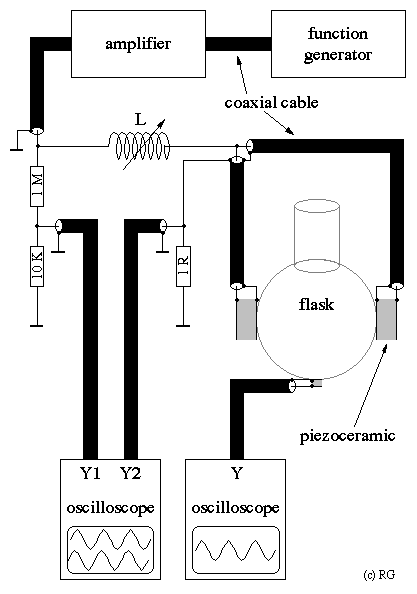
Fix the microphone transducer on the bottom of the flask.
One final hint: You really have to glue the transducers. Don't try any
clamp-press-or-something-stuff. It won't work.
Persuade one bubble to glow:
- Prepare degassed Water:
- with a vacuum pump:
Fill the Erlenmeyer flask or the bottle up to the half with distilled water and pump off the air until the gas is completely pulled off the water (at least 15 minutes). - with an Erlenmeyer flask:
Fill the Erlenmeyer flask up to the half with distilled water, close it with the airtight stopper and heat it. Leave it boiling with an open hose for about 15 minutes. Take it off the heat and clamp the hose. Let it cool down. - with a drinking bottle:
Fill the bottle up to the half with distilled water, put the cap loosely on top allowing the air to escape and heat it. Leave it boiling for about 15 minutes. Take it off the heat and close the cap completely. Let it cool down. Don't bother me with "my bottle exploded, what was wrong?"-stuff; While the bottle is heated it mustn't be closed! - Clean the flask thoroughly.
- Open your vessel with the degassed water. Pour the water into your flask letting it run down the glass. Be careful not to produce bubbles while filling. Fill it up to the neck, so the water is nearly spherical shaped.
-
Find the acoustic resonance:
By-pass the coil and set the sinus generator to 26 kHz. Display the microphone signal on your oscilloscope. Now change the frequency slowly to find the maximum amplitude of the signal. There may be several local maximums around that frequency, but in most cases you'll have to select the absolute maximum (i.e. the highest peak). If you got a sweep generator, it might be helpful to display a 20-30 kHz sweep on the scope. The acoustic resonance appears as a some 100 Hz broad peak. If you found the resonance, remove the by-pass. -
Adjust the inductance:
Display voltage and current on your oscilloscope so you can see the phase shift. Adjust the core/change the distance between the coils until the phase shift is zero. If you got a sweep generator, it might be helpful to display a 20-30 kHz sweep of the microphone signal on the scope. The electric resonance appears as a 1 kHz broad peak overlaying the acoustic resonance. - Choose a low driving amplitude, e.g. 100 mV peak-to-peak on your oscilloscope.
- Watch the microphone signal: It shows a pure sinusoidal voltage. If ripples are on the signal, there are some bubbles in the flask. Leave them alone a minute or two with the driving voltage switched off. If they don't vanish, your water contains too much air; you have to degas it more carefully. Ripples may also indicate a poor contact between a transducer and the flask. The epoxy has to cover the whole transducer and no air may be between transducer and flask. Air between epoxy and flask appears as a reflecting area.
-
Create a bubble:
Extract some water with the syringe or the eyedropper. With the syringe let a drop fall on the surface of the water. This creates a bunch of tiny bubbles. Some of them will dissolve whereas others will drift to the center of the flask and unite. To see them, you have to light them from behind and look against a dark background. A broadened laser beam is really nice and helpful! Watch the microphone signal; Now there should be some ripples on the sinusoidal signal. The ripples are still visible if the bubble is to small to be seen without a laser; So watch the ripples, not the bubble. A high-pass filter improves their visibility. If you see no ripples, increase the voltage and try again. If the ripples quickly vanish, turn the voltage lower and try again. - Slowly increase the driving amplitude. At a certain amplitude the bubble becomes instable and vanishes: No ripples are visible. Turn the voltage lower a bit and create a new bubble.
-
This is the big moment:
Darken the surrounding light and look at the center of the flask. You should see a tiny blue-white dot, like you captured a little star from the night sky. - If no glowing dot is visible: The microphone signal has to give a stable image of the ripples on the scope. Change the driving voltage and perhaps the frequency a bit to achieve that. Increase the driving voltage just below the instability border. You may change the frequency, too, but it isn't that critical.
Once you succeeded, you should be able to reproduce SBSL without difficulties. With this basic setup you may start experimenting. Investigate the parameter range where SBSL is visible. Try other flasks, other liquids (putting glycerine into the water improves SBSL),...
Persuade many bubbles to glow:
- Fill the flask with water up to the neck.
- Find the acoustic resonance.
- Adjust the inductance.
- Increase the driving voltage until you hear a horrible screeching noise, which sounds like your flask is going to crack. Don't be surprised if it does... and don't touch any exposed connection. The sound is produced by cavitation, i.e. by imploding cavities in the water.
- Pay attention not to overheat the coil(s) or transducers.
- You need a very high driving amplitude (maybe some hundred volts). If your amplifier doesn't reach it: To double the voltage, feed the inverted signal to the second (stereo) amplifier channel and use the signal between the two live outputs.
- Darken your room completely. Adapt your eyes, which may take 15 minutes up to half an hour. Look at the flask or at least where you think your flask is (remember: the room is completely darkened). You will see a weak glowing in some areas of the water and sometimes flashes crossing the flask. This is the famous Multi Bubble Sonoluminescence.
References:
- R. A. Hiller, B. P. Barber, Scientific American Feb. 1995, 78
- D. F. Gaitan et al., J. Accoust. Soc. Am. 91, 3166 (1992)
- L. A. Crum, Physics Today Sept. 1994, 22
Manufacturers:
-
Channel Industries, Inc.
839 Ward Drive
Santa Barbara, Calif.
Tel. (805) 967-0171; Fax (805) 683-3420
*** the 3 transducers are offered for $95 *** -
PI Ceramic GmbH
Lindenstraße
D-07589 Lederhose, Germany
Tel. (+49[0]36604) 8820; Fax (+49[0]36604) 88225
*** you may take the PIC 155 type ***